


News
MCC Catastrophic Failure at a Client Facility
BY ADAM MURRAY, Advanced Electrical Services Ltd., a RESA Power company
When a facility experiences a catastrophic electrical failure event, the impact of such events can be devastating to operations, and more importantly, personnel. Just such an event occurred at a gas plant in Alberta, Canada.
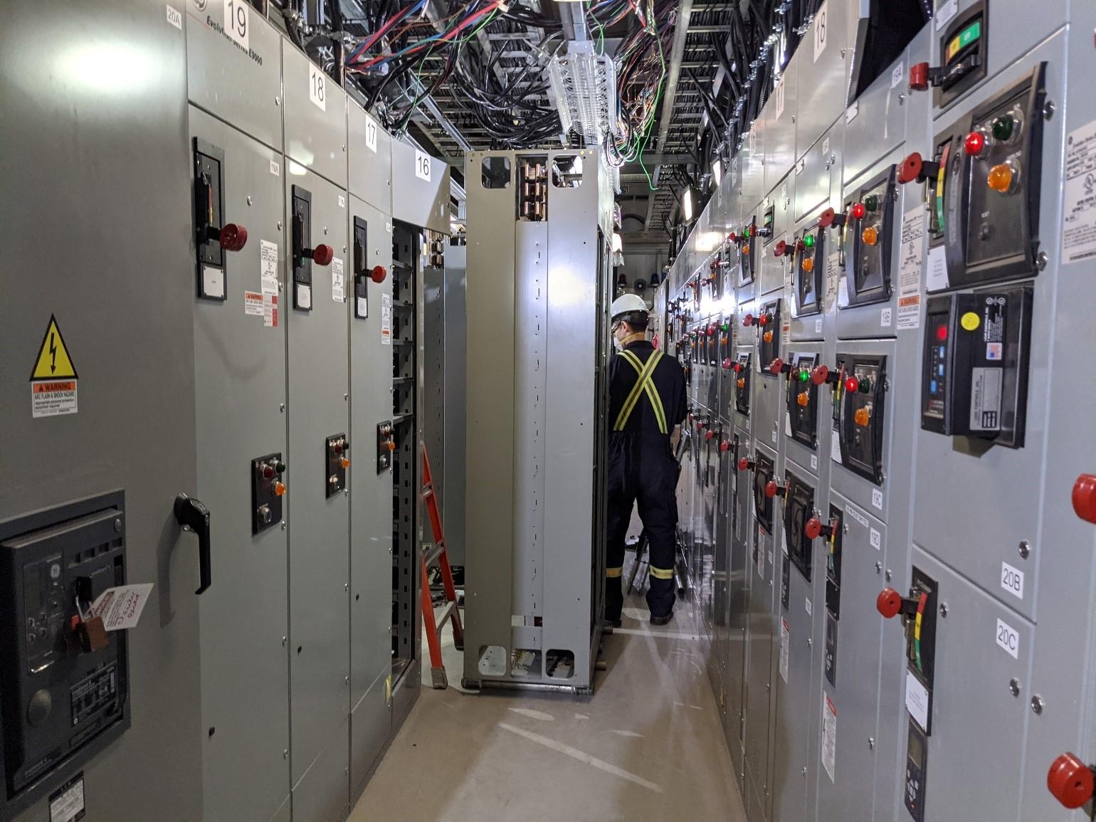
Field service personnel were dispatched to the gas processing plant in northern Alberta, Canada, for emergency repair of a failed 600-volt motor control center (MCC) bus. Before the technicians arrived, the 600-volt bus components had been disassembled by facility personnel to prepare for installation of a new MCC section. For the client, getting the facility back up and operational was more critical than performing an in-depth investigation of the failure.
However, using information and photographs available, the technicians explored potential root causes for the failure. Moisture, humidity, and condensation were discussed but quickly ruled out due to ambient conditions within a functional climate-control unit in the building, which also provided inherently low relative humidity of this area.
Figure 1 shows that the A-phase bus experienced a high degree of heating between the vertical bus connection and the adjacent horizontal bus connection where the eventual failure occurred. This was apparently due to the high level of oxidation on the bus bar, exacerbated by the lack of tin plating.
If there were a loose vertical bus connection, it likely would have dissipated heat into the nearby horizontal connection that was thermally and electrically insulated with vinyl tape. This allowed heat to accumulate within this portion of the bus.
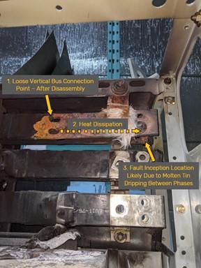
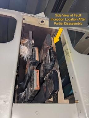
At this point, the A-phase bus bar got hot enough to allow the tin plating to melt, and molten tin to drip down on top of the adjacent B-phase bus. This would have effectively created a conductive path between phases allowing an inadvertent electrical connection and subsequent ionization of surrounding air and an arc flash event. (Figure 2).
The likely root cause of this failure was determined to be loose vertical bus connections that were not recognized during the initial commissioning of the MCC three years prior. As part of the investigation, r previous maintenance records on the failed equipment were requested.
The client stated that no previous maintenance had been performed and no maintenance records exist. This was a key contributor to the failure. The deficiency may have been recognized prior to the eventual catastrophic failure if contact resistance testing had been performed during maintenance.
Lessons Learned
The catastrophic failure of the 600-volt MCC could have been mitigated and potentially avoided during commissioning or maintenance activities by employing several procedures and tools that are available to experienced test technicians:
Recommended Tests
When testing bolted electrical connections, several additional test procedures are recommended:
- All bolted electrical connections should be tested with a low-resistance ohmmeter. The NETA standard does not specify a dc current value,; however, if a higher available test current falls under the confines of the equipment’s rated capacity it should be used, as some high-resistance connections don’t manifest until higher current levels.
- If inspecting a 4,000-amp bus, consider using a higher-output test set and more carefully check the torque on all bolted connections.
- Conversely, if the equipment is only rated for 20-amps, for example, a 10-amp dc low-resistance ohmmeter test can be used if torque cannot be confirmed.
- Torque checks should always supplement electrical contact resistance testing if the connections are accessible. Specific items to be considered for testing include:
- Vertical bus connections accessed by temporarily removing MCC buckets
- Grounding provisions such as safety grounding balls
- Higher – current disconnect switches and breakers (refer to ANSI/NETA ATS and ANSI/NETA MTS for more information)
- Fuse connections (connection only), but be cautious when performing contact resistance around a fuse. A low-current test unit or multimeter can be used if fuse integrity needs to be confirmed.
Theory
Simply put, a high-resistance connection can generally result in two undesirable outcomes:
With loose bolted electrical connections, a hazardous scenario can exist when equipment connections will not sufficiently pass rated current without overheating. This high-resistance connection can create heating modeled by the P = I^2*R formula, where P is equal to power. This could simply be understood to be directly proportional to the heating effect at this poor connection. I and R are equal to current and resistance, respectively.
The heating effect can also be accelerated by items such as well-insulated connections (thermally and electrically), tight enclosed spaces without airflow, and the positive feedback loop of connection having higher resistance as heat increases. A hot general environment, such as an MCC located in a small building with no A/C in the summer will also accelerate the effects of heating.
Downstream equipment can also experience a voltage drop from heating. The magnitude of this drop can be modeled by V = I*R, where I is nominal bus current, and R is the resistance of the connection. The following quote from Fluke Corporation’s website discusses the effect voltage drop can have on current unbalance on electric motors:
“Voltage unbalance at the motor terminals causes high current unbalance, which can be six to 10 times as large as the voltage unbalance. Unbalanced currents lead to torque pulsation, increased vibration and mechanical stress, increased losses, and motor overheating.
ANSI/NEMA standard MG 1 prescribes a 1% limit for voltage unbalance, noting that current unbalance can be expected to be six to 10 times the voltage unbalance on a percent basis. If the current unbalance exceeds 10%, the supply voltages should be corrected to less than 1% unbalance, or the motor must be de-rated.”
-Fluke Corporation
CONCLUSION
The effects of high-resistance connections can ultimately lead to issues with electrical equipment and systems, and these effects are exponentially proportional and can cause major issues for plant equipment.
Adam Murray is the Technical Services Manager at Advanced Electrical Services Ltd (AES). with four years of experience testing and commissioning in the industrial and utility sectors of Western Canada. At AES, Adam is responsible for management of medium- to large-scale electrical commissioning and maintenance projects for the many clients we support across Western Canada. He is a NETA Level III Technician who studied electrical engineering technology at the Southern Alberta Institute of Technology.
About RESA Power
RESA Power, a portfolio company of Investcorp, a global alternative investment firm, is a market leader in power systems services and life extension solutions for power distribution equipment used in mission-critical environments. With locations across the United States and Canada, RESA Power is uniquely capable of ensuring its customers’ critical power systems are safe, reliable, and operating at peak efficiency. The technicians and engineers at RESA Power are experts in testing and servicing transformers, relays, breakers, and other key components of power distribution and control systems. RESA Power also provides quick turn-around custom manufactured or retrofit switchgear and breaker solutions and maintains an extensive inventory of obsolete and hard-to-find components. For more information about how to join the RESA Power group, visit www.resapower.com or follow @RESAPower on LinkedIn